The world of industrial filtration is continually evolving, offering progressive solutions that cater to various industries including power plants, biopharmaceutical, petrochemical, among others. One such revolutionary innovation is the High Flow Filter Element. The genesis of this technology has indubitably ignited a seismic shift in how industries respond to their filtration needs, offering an unsurpassed efficiency level. This examination aims to unravel the fundamentals of high flow filter elements, including their construction, applications, advantages, principle of operation, and overall significance in today's industrial sectors.
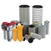
Let's dive into what a High Flow Filter Element is in its simplest understanding. It adopts fine polypropylene or glass fiber membrane as the filter material with a large diameter of six inches or 152mm. It stands out from its peers owing to its design that largely foregoes a central rod but uses a one-way opening coupled with a uniquely designed liquid flow direction from the inside to the outside. This configuration is assuredly a win-win as it guarantees that all the pollutant particles are intercepted inside the filter element, effectively leading to a cleaner and safer output.
The revolutionary design of the High Flow Filter Element contributes to ultra-large flow reduction, enabling it to consume fewer filter elements and filters under a similar flow application. This effectively translates into significant savings on equipment outlay and also shrinks labor cost. The user can customize the filter based on actual working conditions, making it an adaptable choice across diverse industry requirements.
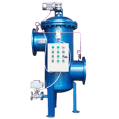
In terms of connection, the High Flow Filter utilizes a sealed interface design to prevent leakages and improve the safety of the filtering process. Its interface employs a rubber sealing ring that is safe, non-toxic, and effectively hinders any leakage. This significantly simplifies the installation process while also reducing the risk of side flow, ensuring the sealing and reliability of the filtration.
Speaking about installation, the structure of High Flow Filter Element epitomizes simplicity. It offers a compact structure, easy to move, and straightforward maintenance, making it a versatile and user-friendly choice for industries.

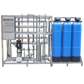
When it comes to its application, this filter technology offers an extensive range that suits a myriad of requirements. The applications generally include Reverse Osmosis (RO) security filtration, seawater desalination pretreatment, filtration of condensed water in power plants, and the filtration of raw materials, solvents, and water in the biopharmaceutical industry. The filter media it can handle includes water suspended solids, particulate matter, water fouling, bacteria and algae, rust, and more.
The working principle of the High Flow Filter Element is quite intriguing. It harbors a novel patented discounting of the filter element, combined with a large diameter, reducing the number of filters and the requirements for the size of the filter housing.
The high flow filter element has heralded a new era in the industrial filtration sector, offering much-needed relief in terms of efficiency, cost-effectiveness, and adaptability. The use of high-quality materials ensures the durability of the high flow filter element and prevents secondary pollution. These factors, combined with its simplicity and reliability, are the reasons why industries are rapidly shifting to the use of high flow filter elements. All in all, it represents a progressive and smart allocation of resources that align favorably with the demanding industrial landscape.
In the petrochemical industry, the adoption of High Flow Filter Elements brings about a range of specific benefits:
Increased Productivity: As the High Flow Filter Element boasts a higher flow rate, it allows for a greater throughput of materials to be processed. With this, more fluid can be filtered in less time, leading to an increase in productivity.
Decreased Waste: The design of these filter elements reduces the number of replacements needed. This leads to decreased waste generation, enhancing the environmental sustainability of operations in the petrochemical industry.
Reduced Operating and Labor Costs: Fewer filter elements imply less frequent replacements, leading to lower labor and logistical costs. The large, pleated filters provide a vast filtration area, contributing to a lower frequency of filter replacements.
Dirt Holding Capacity: High Flow Filter Elements have an incredibly large pollutant holding capacity. Raw materials in petrochemical industries often contain high amounts of particulates, making these filters an attractive, efficient option.
Filtration Efficiency: Due to its technical advantages and unique design, the high flow filter element can balance the relationship between filtration efficiency and pressure drop, reducing energy consumption while maintaining a high filtration efficiency.
Flexibility: They provide a wider flow range, making operations more versatile.
By having such benefits, the High Flow Filter Element becomes an essential tool to significantly facilitate and optimize processes in the petrochemical sector.
The High Flow Filter Element stands out in the industrial landscape with its flexible characteristics, making it a preferred asset in petrochemical sector operations.
Customization: One of the chief reasons for the flexibility of High Flow Filter Elements is the option for customization according to working conditions. It allows the users to adapt the filters as per their specific processing requirements, accommodating diverse types of fluids and flow rates.
Broad Spectrum Filtration: These filters can deal with a broad spectrum of particulates in fluid, varying in type and size. They can handle suspended solids, particulate matter, bacterial growth, etc., making them versatile to address a diverse range of operational considerations in the petrochemical sector.
Wider Flow Range: High Flow Filter Elements ensures a large flow range, maximizing both high flow and low flow filtration tasks. It adds to its suitability across different processes.
Durability: The overall polypropylene design and hot-melt welding treatment of these filters resist corrosion, enhancing their reliability and lifespan even in diverse operating conditions.
Variety of Filter Media Options: Various filter media, such as polypropylene or glass fibers, could be utilized for different applications within the petrochemical industry, allowing customization based on specific filtration requirements.
Space Efficiency: The large diameter and folded design increases the filter area, providing more filtration capacity per unit volume. This feature allows the use of smaller systems or fewer filter units for space-constrained applications.
Overall, the High Flow Filter Elements accord petrochemical operations greater control over their filtration processes, meet different operational requirements, and lower operational costs - marking it as a notably flexible option.
Customization options for High Flow Filter Elements, particularly suited for the petrochemical sector, primarily focus on the following areas:
Filter Material: Depending on the specific filtration needs, users can request customized filter media. This can range from deep fine polypropylene to glass fiber membranes, each of which has different filtration characteristics.
Filter Size and Diameter: Given the varied scale of operations in the petrochemical industry, users might require filter elements of specific sizes and diameters to ensure they fit perfectly within their filtration system.
Sealing Interface Design: The filter's sealing interface can also be customized to fit perfectly with the housing, mitigating the risk of leakages.
Filter Prefection Level: The preference level or the fineness of filtration can also be customized. Users can choose specific filters that remove particles of certain sizes.
Filter Housing: For those preferring a complete solution, the filter housing can also be customized according to the users' requirements to accommodate multiple filter elements.
Filter Flow Rate: Depending on the volume of liquid to be filtered, users can customize the filter's flow rate, with single flow designs ranging between 50 to 70m3/H and up.
Chemical Resistance: Petrochemical operations often involve processing corrosive and chemically aggressive substances. Hence, filters can be customized to be resistant to certain chemicals to ensure their longevity and effectiveness in such conditions.
Gasket/Seal Material: From silicone rubber, ethylene propylene rubber, nitrile rubber to fluorine rubber, the type of gasket or seal can be chosen based on the specific performance needs.
The customization capabilities of High Flow Filter Elements make them highly adaptable to the diverse needs within the petrochemical industry, thereby enabling more effective and efficient filtration processes.
High Flow Filter Elements can be customized to withstand corrosive substances prevalent in the petrochemical industry. Here are some of the ways in which these adaptions can be implemented:
Material Choice - The material used in the construction of the filter elements can be specifically tailored to resist corrosion. For instance, using materials like stainless steel, titanium, or corrosion-resistant alloys can provide superior resistance to corrosive substances.
Coatings - Coatings can be applied to filter elements, adding a layer of protection that resists the chemical reaction leading to corrosion. Specialized coatings such as Teflon or similar materials can provide significant protection.
Chemically Resistant Filter Material - The filter media itself can be made of materials that resist chemical corrosion. For example, glass fiber membranes offer resistance to various corrosive chemicals and can be an ideal choice for operating in harsh conditions.
Seal/Gasket Material - Seals or gaskets made from chemically resistant material like fluorine rubber can be used to prevent leaks and withstand aggressive chemicals.
Polypropylene Construction - Many High Flow Filter Elements use all-polypropylene construction, which holds up well against many corrosive substances. Polypropylene is known for its resistance to acids, bases, and other aggressive chemicals.
Filter Housing Material - Filter housing materials can be made of a corrosion-resistant material or coated with corrosion-resistant materials to preserve the integrity of the whole filtration system.
Through these ways, the High Flow Filter Element can be made capable of tolerating the harsh, corrosive environments that are commonly encountered throughout the petrochemical industry.

Various corrosion-resistant materials can be used in the construction of High Flow Filter Elements to tackle corrosive substances in the petrochemical industry. Each has its advantages and is suited to deal with specific types of corrosive environments. Here are a few examples:
Stainless Steel: This material is often chosen for its overall strength and resistance to both rust and corrosion. In particular, types 316 and 316L are often used for their superior resistance to chemical attack compared to other grades.
Titanium: Titanium possesses excellent resistance to a wide range of corrosive substances, including chlorides, seawater, and chlorine, making it an excellent choice for high-corrosion environments.
Hastelloy: This is a superalloy that provides excellent resistance to corrosion in a wide range of severe environments. It's often used in situations where other materials might fail.
Super Duplex Stainless Steel: This material is known for its high corrosion resistance, particularly resistance to stress corrosion cracking, crevice corrosion, and pitting.
Nylon: A synthetic thermoplastic material that is resistant to most oils and fuels, many types of chemicals, and salt water.
Polypropylene: It is resistant to acids, bases, and other aggressive chemicals, making it an excellent material in many corrosive situations.
Teflon (PTFE): Teflon is chemically inert and known for its ability to withstand aggressive chemical environments. It's often used as a coating for filter elements due to its exceptional properties.
Viton: Also known as fluorocarbon rubber, Viton has excellent chemical resistance properties, particularly against hydrocarbons, oils, acids, and chemicals.
These materials help to ensure that the High Flow Filter Elements can handle even the most corrosive environments found in many petrochemical applications.
Hastelloy, being a superalloy, has a very broad range of applications within corrosive environments, due to its corrosion and high-temperature resistance, making it a popular choice for High Flow Filter Elements. Some of the specific applications where it is commonly used include:
High-Temperature Applications: Hastelloy X, particularly, is renowned for its high-temperature corrosion resistance, which makes it highly suitable for environments where both high temperatures and corrosive substances are present.
Oxidizing and Reducing Environments: Hastelloy C-22 has shown excellent resistance in both oxidizing and reducing environments. It continues to deliver good results even when exposed to strong corrosive substances.
Harsh Industrial Environments: Over the years, due to its corrosion and high-temperature resistance, Hastelloy has been extensively used in very harsh industrial settings.
Filter Cartridges: Specific Hastelloy grades like C276 and C22 are used in the construction of filter cartridges that demand exceptional corrosion resistance.
Overall, Hastelloy's robustness and adaptability make it a preferred choice for high flow filter elements across diverse corrosive environments in the petrochemical industry. It is recognized for its ability to maintain structural integrity and performance under extreme conditions.
Hastelloy C-22, a nickel-chromium-molybdenum-tungsten alloy, is recognized and utilized for its exceptional resistance to both oxidizing and reducing environments due to several distinct properties. Here are the key aspects that make it suitable:
Balance of Chromium and Molybdenum: Hastelloy C-22 presents an enhanced chromium, molybdenum and tungsten content. This robust combination provides this superalloy with excellent resistance to both oxidizing and reducing agents.
Corrosion Resistance: Hastelloy C-22 is outstandingly resistant to pitting, crevice corrosion and stress corrosion cracking. It can withstand a wide range of aggressive chemicals, including mixtures containing oxidizing and reducing substances.
Lower Carbon Content: This grade of Hastelloy has a lower carbon content that minimizes grain boundary carbide precipitation during welding. This ensures improved resistance to intergranular corrosion, which can be an issue in both oxidizing and reducing conditions.
Versatile Chemical Compatibility: It can tolerate a broad range of pH values and can be used in environments with a wide variety of corrosive substances. This trait makes it suitable for use in processes where the nature of the corrosion source may vary.
Temperature Resistance: Hastelloy C-22 is known for its ability to maintain its corrosion resistance over a wide range of temperatures in both oxidizing and reducing conditions. It is functional over a significant range of high temperatures and is not prone to the temperature fluctuations that can affect performance in these environments.
Given these specifications, Hastelloy C-22 has been proven to provide dependable performance in challenging environments where other materials may fail – making it a popular choice in the petrochemical industry for High Flow Filter Elements.
Hastelloy C-22 is a nickel-chromium-molybdenum alloy with tungsten added. The unique combination of these elements gives it several desirable features that make it suitable for use in both oxidizing and reducing environments. Here are the key properties:
Excellent Corrosion Resistance: Hastelloy C-22 is lauded for its resistance to a wide variety of corrosive media, including oxidizing and reducing environments. It stands up well against oxidizers such as ferric and cupric chlorides, chlorine, and hot contaminated solutions like nitric acid and organic acids.
Resistance to Pitting and Crevice Corrosion: The alloy exhibits superior resistance to both pitting and crevice corrosion, two common problems in environments that oscillate between oxidation and reduction.
High Chromium and Molybdenum Content: The high chromium and molybdenum content provides excellent resistance to oxidizing media while tungsten and molybdenum confer resistance to reducing media.
Lower Carbon Content: The lower carbon content of Hastelloy C-22 reduces the precipitation of grain boundary carbides during welding ensuring the alloy maintains its resistance in as-welded structures, key for applications in oxidizing and reducing conditions.
High Temperature Stability: Hastelloy C-22 retains its stability and corrosion resistance even at high temperatures which could be found in many oxidizing or reducing industrial processes.
Multi-purpose Versatility: The alloy's balanced combination of nickel, chromium, molybdenum, and tungsten allows it to withstand a wide variety of severe environments, making it suitable in many industries where both oxidizing and reducing conditions are encountered.
Together these properties allow Hastelloy C-22 to successfully perform in demanding environments, which include severe oxidizing and reducing conditions, which standard stainless steels and even other high-performance materials cannot withstand.
The risk of brittleness in welded structures greatly depends on the carbon content of particular alloys. Here's how:
Higher Carbon Content: Alloys with a higher carbon content are noted for their hardness and strength, which might appear advantageous. However, when these alloys are exposed to the high temperatures involved in welding, the carbon atoms within the alloy can combine with other elements to form compounds such as carbides. These carbides often precipitate at the grain boundaries, which results in a phenomenon known as "grain boundary carbide precipitation". This generally makes the areas around the weld and in the heat affected zone more rigid and susceptible to brittleness, leading to a decreased ability of the material to absorb impact energy, rendering it more prone to cracking under stress or impact. This is a particular problem for conventional stainless steels, which are often relatively high in carbon.
Lower Carbon Content: On the other hand, alloys with lower carbon content, like Hastelloy C-22, are less inclined to form these carbides during the welding process as there are fewer available carbon atoms. This significantly reduces the risk of grain boundary carbide precipitation, maintaining pliability and strength in the weld area and the heat-affected zone, thus reducing the risk of brittleness. In addition to preserving the material's fundamental toughness, the lower carbon content also ensures better resistance to intergranular corrosion, which can cause severe damage to a structure's integrity over time.
Given all of these factors, alloys with lower carbon content are typically preferred for applications where welding is involved, especially when the welded structures are delegated to serve in high-stress or high-impact conditions.
The carbon content in an alloy plays a crucial role in determining the susceptibility of welded structures to intergranular corrosion, and here's how:
Increased Susceptibility in High Carbon Alloys: During the welding process of high carbon alloys, the intense heat involved can cause carbon in the alloy to react with chromium to form chromium carbides. These chromium carbides tend to precipitate, or gather, at the grain boundaries of the metal structure. This phenomenon is known as grain boundary carbide precipitation. This precipitation depletes the area around the grain boundaries of chromium, making these areas less resistant to corrosion. With exposure to a corrosive environment, these less-protected grain boundaries can corrode, a process known as intergranular corrosion.
Reduced Susceptibility in Low Carbon Alloys: In contrast, low carbon alloys have a significantly reduced tendency to form chromium carbides during welding due to their low carbon content. With fewer chromium carbides forming, the chromium level around the grain boundaries remains high, thus providing better corrosion resistance. Therefore, these alloys are much less susceptible to intergranular corrosion.
In summary, the carbon content of an alloy is a major factor in its susceptibility to intergranular corrosion in welded structures. Alloys with lower carbon content, like Hastelloy C-22, offer greater resistance to this type of corrosion, which is particularly beneficial in corrosive environments. They maintain the alloy's inherent corrosion resistance in the heat-affected zone of the weld, thus preserving the integrity and longevity of the welded structures.
Chromium is a key element in alloys and it plays a pivotal role in enhancing the corrosion resistance of these materials. Its function remains crucial across varying levels of carbon content and here's how it works:
Passive Layer Formation: The primary reason chromium is added to alloys is to boost corrosion resistance. Chromium reacts with oxygen in the environment to form a thin, stable, adhering, and self-healing layer of chromium oxide on the surface of the alloy. This chromium oxide layer, often referred to as a "passive layer", acts as a barrier that prevents further corrosion by blocking oxygen diffusion to the underlying metal.
Alloys with Higher Carbon Content: However, when an alloy contains a higher level of carbon, during the welding process, the heat might cause the chromium in the alloy to combine with carbon to create chromium carbides (a phenomenon called carbide precipitation), particularly along the grain boundaries. This leaves the regions nearby with less chromium, tricking the formation of the protective chromium oxide layer and making those areas less resistant to corrosion. This is known as intergranular corrosion, and it's particularly prevalent in the heat-affected zones (HAZ) of welded structures.
Alloys with Lower Carbon Content: In contrast, alloys with lower carbon content, such as Hastelloy C-22, there's less probability of chromium carbides formation because there is not enough carbon to react with chromium. This ensures the chromium available in the alloy can perform its intended role of enhancing corrosion resistance throughout the alloy, even in the heat-affected zones of welds.
In conclusion, chromium's ability to provide corrosion resistance can be hindered in alloys with higher carbon content, especially after welding. Therefore, for optimum corrosion resistance, particularly in welded components, it's often preferable to use a lower-carbon alloy.
Carbide precipitation, also known as intergranular corrosion, is a process that occurs in stainless steels and other alloys. Let me explain it further:
Carbide Precipitation: In a nutshell, carbide precipitation occurs in alloys with higher carbon content when these alloys are heated within a certain temperature range, say 800 to 1400 degrees Fahrenheit. The heat causes the carbon in the steel to react with the chromium to form chromium carbides. These chromium carbides are formed at the grain boundaries of the crystalline structure of the metal.
Impact on Corrosion Resistance: Chromium is a vital element in stainless steel that prevents corrosion. It accomplishes this by forming a thin layer of chromium oxide on the surface of the steel, which is impermeable to both air and water. However, when carbide precipitation occurs, the chromium within the steel is essentially bound up with the carbon, making it unavailable to form the protective oxide layer. This reduction of chromium in the lattice structure leads to areas of the alloy becoming vulnerable to corrosive media, which can adversely affect its corrosion resistance. This is particularly apparent along the grain boundaries, leading to a phenomenon known as intergranular corrosion.
Effect on Welded Structures: This process is especially relevant in the weld decay of stainless steel fabrications, where the heat-affected zones (HAZ) provide the ideal temperatures for carbide precipitation to occur. For welded structures made of alloys with high carbon content, carbide precipitation can lead to a significant decrease in corrosion resistance, especially at the zone near the weld.
Conversely, 'low carbon' or 'extra low carbon' variants of alloys are used to prevent this occurrence, where carbon content is typically kept below 0.03%. The lower carbon content reduces the amount of carbide precipitation during welding, thereby reducing the susceptibility to intergranular corrosion in the heat-affected zones of the welds. This principle is especially important in many forms of life-sustaining applications, like those in chemical process and power generation industries.
During the carbide precipitation process, the chromium in the steel plays a pivotal role. Essentially, in alloys with higher carbon content, when the alloy is subjected to high temperatures (typically between 800 to 1400 degrees Fahrenheit), the carbon in the metal reacts with chromium forming chromium carbides.
This reaction occurs preferentially at the grain boundaries of the metal's crystalline structure, as these areas provide the path of least resistance for the diffusion of carbon atoms. In effect, a sort of chromium depletion zone is created in the areas adjacent to the grain boundaries due to its consumption in the formation of chromium carbides. This area of chromium depletion is consequently less resistant to corrosive media.
This is because the chromium, which is primarily responsible for the alloy's corrosion resistance due to the formation of the protective chromium oxide layer on the alloy's surface, is no longer available in necessary quantities to form this protective layer. The result is an increased susceptibility to intergranular, or "between the grains", corrosion in the areas surrounding the grain boundaries.
Therefore, during carbide precipitation, though chromium is not physically removed from the steel, it becomes 'tied up' in a chemical reaction with carbon, consequently reducing the corrosion resistance of the steel. This is particularly relevant in the heat-affected zones (HAZ) of welded structures.
Chromium depletion in the heat-affected zones (HAZ) of welded structures has a number of profound implications, generally resulting in different types of corrosion and weakened structural integrities. Here's a rundown:
Intergranular Corrosion: The most significant implication is the enhanced risk of intergranular corrosion. Because of chromium depletion in the HAZ, a protective chromium oxide layer cannot form readily in these areas, making them more susceptible to oxidative and corrosive environments.
Pitting and Crevice Corrosion: Areas of reduced chromium are also more prone to localized forms of corrosion such as pitting and crevice corrosion.
Stress Corrosion Cracking: Chromium depletion can also increase susceptibility to Stress Corrosion Cracking (SCC).
Lowered Mechanical Properties: In severe cases, such as prolonged exposure to high temperatures or several thermal cycles, the mechanical properties such as toughness and tensile strength might deteriorate at these chromium depleted zones, which could lead to structural failure.
To prevent chromium depletion and its undesirable effects, several techniques and materials are employed. These include:
Using low-carbon or extra-low-carbon variants of steel (e.g., 316L, where 'L' stands for 'Low carbon') that reduce the amount of chromium carbide precipitation during welding.
Post-weld heat treatments that dissolve the chromium carbides and allow the chromium to diffuse back into the steel lattice, restoring the protective oxide layer.
Employing welding techniques that minimize the time the material spends at the sensitization temperature (around 800°F-1400°F).
The choice between these techniques depends on specific requirements, the nature of the components involved, and other performance-related factors.
There are several methods generally adopted to prevent chromium depletion and its associated adverse effects in welded structures. These are mostly based around choice of materials, thermal treatments, or modifying the welding process itself. Here are a few key methods:
Use of Low-carbon Variants of Steel: Choosing 'L-grades' or 'low-carbon' versions of steel such as 304L or 316L which typically have less than 0.03% of carbon can help reduce the amount of chromium carbide that forms in the heat affected zones. So, less chromium is used to form chromium carbides, meaning there’s more chromium available to combat corrosion.
Use of Stabilized Grades of Steel: Some types of stainless steel are made with added alloys – titanium in Type 321 and columbium and tantalum in Type 347 – that preferentially combine with carbon and prevent the formation of chromium carbides.
Post-weld Heat Treatments: They are used to mitigate the loss of corrosion resistance. In the heat treatment process, the welded part is heated to a high temperature where chromium carbides are dissolved and the chromium is diffused back into the steel matrix. Once cooled, the chromium is then available again to form the protective oxide layer.
Solution Annealing: This involves heating the steel to a high temperature, holding it there for a time, and then cooling it really fast. During this process, the chromium carbides can dissolve back into the matrix, restoring the structure and the corrosion resistance of the steel.
Welding Techniques: Using a controlled-heat input during welding can prevent chromium depletion. This includes techniques like low-temperature welding, short-arc welding, or welding with a low-heat input electrode. These techniques aim at limiting the time, and thus the opportunity, for the chromium and the carbon to react.
Use of Inert Gas: The use of an inert gas during welding also helps to limit the formation of unwanted compounds, thus reducing the potential depletion of chromium in the weld and its heat-affected zones.
Choosing which method to use requires proper understanding of the specific requirements and constraints of a given application or piece of infrastructure that's being worked on.
Inert gases are used during welding primarily for shielding the welding area from the atmospheric gases such as oxygen, nitrogen, and water vapor. In the context of preventing chromium depletion in heat-affected zones, using inert gas has several benefits:
Prevents Oxidation of Chromium: Inert gas protects the molten weld pool from reacting with oxygen in the atmosphere. This is crucial in the context of chromium as it readily forms an oxide if exposed to oxygen at elevated temperatures, leading to less chromium being available to combat corrosion or form chromium carbides.
Prevents Nitriding: Nitrogen, another atmospheric gas, also contributes to nitride formation in certain metals. Nitrides can have similar potent effects as carbides, causing an imbalance in the composition and potentially leading to chromium depletion. An inert gas shield prevents this.
Provides Cleaner Welds: Utilizing an inert gas during weld operations results in cleaner welds free of porosity, thus preventing the trapping of corrosive agents in the welds which can lead to pitting or crevice corrosion over time.
Surface Quality: Inert gas shielding generally enhances the surface quality of the weld metals, which can result in a more uniform weld bead and more appealing cosmetic appearance.
Increased Structural Integrity: By maintaining the original metal characteristics, including preserving the chromium in heat-affected zones, the final welded structure enjoys increased resistance to intergranular corrosion, pitting, and other types of damage.
Commonly used inert gases in welding, especially when working with stainless steel and other chromium-containing alloys, include argon and helium or a mixture of these. They don't react with metal or cause alloying, thus effectively preventing unwanted metallurgical reactions.
Inert gas plays a critical role in preventing nitriding in the heat-affected zones (HAZ) of welded structures. Nitriding is a process where nitrogen in the atmosphere can react and incorporate into metals when exposed to high temperatures, as in welding. This can have several detrimental effects on the material properties, including increased hardness and brittleness, and reduced ductility.
Here's how inert gas helps to prevent this:
Forming a Protective Atmosphere: The primary role of an inert gas in welding is to create a shield around the molten weld pool and the heat-affected zone. This shield prevents the weld area from coming into contact with the atmosphere, thus preventing nitrogen as well as other atmospheric gases from reaching the heated metal and causing nitriding.
Preventing Nitride Formation: Some metals are more prone to nitriding than others. When nitrogen is allowed to contact these metals at a high temperature, it can form nitrides, which are hard and brittle compounds that can alter the mechanical properties of the material. By maintaining an inert atmosphere during welding, this nitride formation is avoided.
Preservation of Material Characteristics: By preventing nitriding, inert gas shielding can help preserve the desired mechanical and chemical properties of the welded materials, including ductility, toughness, and corrosion resistance.
The most commonly used inert gases in welding are argon and helium or a mixture of these because they don't react with metals or cause alloying effects. They are termed 'inert' precisely because they prevent unwanted metallurgical reactions such as nitriding from happening during welding.
Inert gas shielding works by displacing the atmospheric air in and around the welding area. Here is the detailed process of how it creates a protective shield during the welding process:
Gas Dispersion: When you start welding, the welding gun releases an inert gas—usually argon or helium, or a mixture of these. This gas flows out around the welding arc and envelops the area where the extreme heat of the arc would otherwise subject the material being welded to atmospheric gases.
Displacement of Atmospheric Gases: The inert gas being denser than the surrounding atmospheric air displaces oxygen, nitrogen, and other gases that can react with the molten metal, effectively preventing them from coming into contact with the hot welding material.
Formation of Protective Shield: The surrounding inert gas does not react with the metal workpiece or with the filler metal, forming a protective 'bubble' or 'shield' that prevents the atmospheric gases from reaching the weld pool and the adjacent heat-affected zone.
Maintained Protection During Solidification: The inert gas continues to shield the area until the molten metal has solidified, helping to ensure the integrity and purity of the weld even as it cools.
The effective shielding of the weld area from atmospheric gases prevents oxidation, nitriding, and other reactions that could weaken the weld, promote rust or other corrosion, or affect the metal's structure on a microscopic level. These shielding gases therefore play a pivotal role in many welding processes, especially those implicating metals prone to oxidation and nitriding, like stainless steel and high-chromium alloys.
The primary gases that are displaced by the inert gas during the welding process are the components of regular atmospheric air. These include:
Oxygen (O2): Oxygen can readily react with hot metal, leading to oxidation and compromising the structural integrity of the weld.
Nitrogen (N2): Similar to oxygen, nitrogen can also react with certain metals at high temperatures, leading to nitride formation, which can affect the weld's properties, particularly its hardness and ductility.
Water Vapor (H2O): The presence of water vapor can result in hydrogen getting into the weld, which can cause porosity and cracking, particularly when high-strength steels are being welded.
Carbon Dioxide (CO2): In small amounts in atmospheric air, CO2 can also be present around the welding arc. It can potentially react with the metal, leading to carbide formation depending on the type of metal being welded.
By displacing these gases with an inert gas (such as argon or helium), the interaction between the weld pool and the atmospheric air components is prevented. As a result, the integrity, appearance, and overall quality of the welds are greatly enhanced.
The presence of water vapor can have a significant impact on the welding process. When metal is exposed to high temperatures during welding, the water vapor can decompose, introducing hydrogen into the molten weld pool. This can lead to several issues:
Hydrogen Induced Cracking or Cold Cracking: This is one of the most serious problems. Hydrogen soluble in liquid metal can become trapped as the metal solidifies. Any excess hydrogen that cannot escape may form gas pockets, leading to internal stresses. As the metal cools to room temperature, these trapped hydrogen atoms can combine to form hydrogen gas, causing small cracks within the metal. This phenomenon, known as hydrogen induced cracking or cold cracking, can severely weaken the weld and the surrounding metal.
Porosity: Hydrogen in the weld metal can lead to porosity, where multiple small gas pockets or "pores" form in the solidified weld bead. Porosity can decrease the strength of the weld and lead to failure under stress.
Undercutting and Underfill: Moisture from water vapor can cause irregularities in the weld bead, leading to problems like undercutting (where the edge of the weld has a concave shape) or underfill (where the weld metal does not fill the joint completely). Both of these can weaken the weld and make it more likely to fail under strain.
Arc Instability: Water vapor can affect the stability of the welding arc, causing it to stutter or flutter. This can make it difficult to maintain a consistent welding pool and can result in uneven welds.
These are some reasons why it's essential to ensure dry conditions before welding, using desiccants with welding rods and wires, or preheating the metal to drive off moisture.
Hydrogen induced cracking, also known as hydrogen assisted cracking or cold cracking, is a significant concern in welding due to its detrimental impact on the quality and safety of the welded structures. Here are some of the potential consequences:
Structural Integrity: Cracks formed by hydrogen induced cracking compromise the structural integrity of the weld and the overall component or structure. These weak spots can ultimately cause failure under stress or load, leading to a breakdown of machinery, infrastructure, or even causing safety hazards in high-stress structures like bridges or buildings.
Delayed Failure: Hydrogen induced cracking may not appear immediately after welding; it can occur hours or even days later. This delay makes detection difficult during routine quality checks immediately post-welding, risking the integrity of the structure in the long term.
Repair Difficulty and Cost: Detecting and repairing hydrogen induced cracks is challenging and costly. Since the cracks often occur beneath the surface, advanced methods like ultrasonic testing may be needed for detection. Repairing these defects could require a complete grind out and re-weld of the affected area, adding time and cost to the project.
Reduced Material Properties: Hydrogen induced cracks can change the properties of the material being welded, reducing hardness and toughness. This change can further weaken the structure or component, reducing its lifespan and effectiveness.
Safety Risk: In worst-case scenarios, hydrogen induced cracking can lead to catastrophic failures in critical applications, such as pressure vessels, offshore structures, and automotive components, posing a significant safety risk.
Due to these potential implications, it's vital to control and minimize the risk of hydrogen induced cracking by following proper welding procedures, including using low-hydrogen electrodes, preheating the metal, and using controlled post-weld heat treatments.
Induced hydrogen cracks in welding can indeed pose significant challenges both in terms of detection and repair. Here are some of the issues:
Delayed Appearance: Hydrogen-induced cracks often don't appear immediately post-welding. They may take hours, days, or even weeks to become visible, presenting a major detection challenge. Since components are usually inspected shortly after the welding process, these cracks can go undetected until they cause problems.
Internal Cracks: Often, these cracks are not surface cracks, but exist internally in the weld or heat-affected zone. Since they're not visible on the surface, special non-destructive testing methods, such as ultrasonic testing or radiographic testing, may be required to detect them, increasing the complexity and cost of the inspection process.
Repair Complexity: Once identified, hydrogen induced cracks can be difficult and costly to repair. The affected region must be completely removed, typically by grinding out or gouging out the cracked weld area. After that, the weld joint must be effectively re-welded, which needs skilled personnel to ensure that the same issue does not reoccur.
Recurring Issue: Since the cracking is a result of the presence of hydrogen, unless the root cause of the issue is addressed—such as moisture in the environment, welding consumables, or the material itself—cracks may reappear after the repair.
Preventing Further Cracking: The heat from welding can release hydrogen trapped in other areas of the metal, which can lead to more cracking. Preheating and post-heat treatments need to be controlled precisely to drive out hydrogen without causing additional cracking.
Therefore, preventing hydrogen induced cracking by following proper welding procedures and controls is more optimal than trying to identify and repair them afterward.
Cracks in welding, whether they are surface or internal, can significantly reduce the strength and integrity of a welded joint. Both types present their own distinct challenges and issues:
")
Surface Cracks:
Visibility: Surface cracks are visible to the naked eye or upon a routine visual inspection. This makes their detection easier compared to internal cracks.
Extent: Although visibly evident, it may be challenging to determine the full extent and depth of a surface crack without further investigation, such as dye penetrant or magnetic particle inspection.
Repair: Surface cracks can be typically repaired by grinding the cracked area and re-welding.
Cause: Surface cracks often result from factors like rapid cooling, high weld energy, excessive weld bead, incorrect welding technique, or metallurgical changes in the weld bead or heat-affected zone.
Internal Cracks:
Visibility: As these cracks are hidden within the weld metal or base metal, they are not visible on the surface and cannot be detected through a simple visual inspection.
Detection: Specialized non-destructive testing techniques, such as ultrasonic testing or radiographic testing, are necessary to detect internal cracks.
Repair: Repair of internal cracks is more complex and time-consuming. The cracked section needs to be removed entirely, often through grinding or gouging, before the joint can be re-welded.
Cause: Internal cracks, such as hydrogen-induced cracks, are often caused by contamination of the weld, such as moisture or impurities in the welding materials or base metal.
Overall, while no cracks are desirable in a weld, internal cracks typically represent a more serious problem due to their difficulty in detection and complexity in repair. Extensive quality control and correct welding procedures are needed to avoid both types of cracks.